In order to cut accurately and safely on a tablesaw you need to make sure things are properly aligned. Hopefully your saw’s manufacturer has set things pretty close, but there’s almost always room for improvement. Plus, it’s a good idea to periodically re-check and re-set these alignment values as things can go out of square over time (especially the fence!)
The Measurements
There are 5 main measurements to check on a table saw to ensure accurate (and safe!) cutting:
- Saw blade parallel to T-slots
- Saw blade 90° stop accuracy
- Saw blade 45° stop accuracy
- Saw fence face 90° to table
- Saw fence parallel to T-slots
That list is in order of how often the measurements should be checked. In other words, once you adjust your trunnions so the blade is parallel to the T-slots it’s not likely to go out of alignment very quickly. On the other hand, the saw fence should be regularly checked to ensure it’s in alignment.
Tools Required
There’s a plethora of application-specific tools made for aligning table saws, with each design having varying degrees of accuracy and simplicity of use. Personally, though, I prefer multi-purpose tools. So with that in mind we’re going to cover methods that primarily some very versatile machinist tools, many of which you should probably have in your shop anyway. In particular you’ll need:
- A dial indicator
- A dial test indicator (optional, as you can use a dial indicator, but a DTI is handy)
- An accurate 90° and 45° reference (eg. squares)
- A surface gage, plus an approximately 1″ ground round reference object if your surface gage doesn’t have a curved face (a ball bearing works very well, or a piece of ground rod)
Most of those items you likely have lying around anyway. As for the surface gage, you can usually find used Starretts and shop-made gages on eBay for a good price. For example, I recently picked up 3 shop-made gages for about $40 including shipping. Many people avoid shop-made gages but in most cases they’re excellent choices for hobbyists.
A Note on Accuracy and Cosine Error
Before getting started it’s important to understand a few things about what you’re measuring. First off, be reasonable about what you’re looking for accuracy-wise. You don’t need the fence parallel to the T-slots within 0.001″. There’s no way you’re going to be cutting to that kind of accuracy, and even if you somehow could do so the wood would be expanding and contracting way too much for that kind of accuracy to be of any use.
As well, when using the surface gage keep in mind that if your indicator is not aligned exactly with the workpiece there will be some error with the measurement. This is referred to as
cosine error. Again, considering the accuracy that we’re looking for cosine error won’t usually be a big deal for us as long as we’re roughly aligned properly. But if you, for example, have a dial indicator touching the workpiece at a 45° angle your measurement is going to be off significantly: If you move the workpiece 1/4″ closer to the indicator the indicator will show 1/2″ travel.
Aligning the Blade Parallel to the T-Slots
This is by far the biggest pain of all the jobs. Fortunately, it’s also the one you need to do the least often.
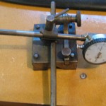
Surface Gage Set up for checking parallelism
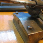
Pins for following T-slot
First, let’s get familiar with the surface gage setup. Attach your dial indicator to your gage so that it looks like the photo to the left.
Now notice the 4 pins on the 4 corners of the gage base. Those pins can be pushed down so that they can follow the T-slot. This allows us to get very accurate readings of parallelism between the T-slot and the blade (and later the fence).
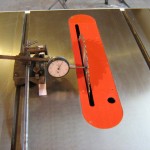
Blade squareness start position
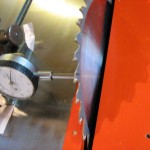
Marked blade
Set up the gage so that the indicator tip is touching the saw blade at a point as low as possible and as close to the operator (ie. you when you’re cutting something) as possible, like in the picture on the left. Make sure that when the gage pins are pushed against the side of the T-slot that the indicator plunger still has some preload on it (ie. it should be pushed in part way).
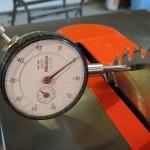
My blade had 0.005" runout
Now for the actual measurement: While holding the gage firmly against one side or the other of the T-slot, and while being careful not to disturb the indicator mount, turn the bezel of the dial indicator to zero it (ie. align the pointer with zero). Then, slide the gage away from the operator (ie. towards the rear of the table) and rotate the blade to align the mark you made earlier. Note the runout, as shown to the right. In my case my General saw had a runout of 0.005″ to the left.
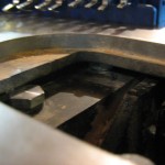
Trunnion bolts
The exact procedure for adjusting alignment will differ from saw to saw. In my case the trunnion bolts were accessible from above the table (thank you General!) using a stubby wrench or a crowfoot socket.
Adjustment is made by loosening the bolts slightly and moving the trunnion over, then retightening. In my case I loosened the front trunnion bolts and used a crowbar to slightly push the trunnion towards the left, to match the left runout I had measured before.
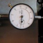
.002" runout
I adjusted the runout to .002″ and tightened the trunnion bolts and re-checked runout. Still good!
Why leave any runout?
Why not set it to 0? Well, we could, but there are a couple reasons why you might not want to. First, .002″ runout is really not much. To give an idea of what we’re dealing with, a typical human hair is about 0.004″ in diameter. So we’re out by half a hair. The second reason I chose to have a little runout is that I primarily cut on the right side of the blade and having a bit of runout to the left gives me a bit of a safety margin against jamming and kickback – two problems typically caused by the distance between the fence and rear of the blade being less than at the front. For this same reason I left some runout on the fence.
Checking the Blade’s 90° Stop
Next up is square the blade at the 90° stop. Before doing this check it’s important that your blade’s adjustment mechanism is well lubricated (something which you should check regularly!) as a hard-to-turn mechanism will throw off the stop position. Then turn the blade to the stop with the normal amount of force that you use when cutting and lock it in position.
In order to set an accurate angle with the surface gage it’s important to have an accurate reference. I’m using machinist squares, but you might choose a combination square, speed square, cylinder square, etc. etc etc. Just make sure it’s relatively accurate.
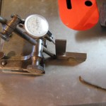
Aligning Using the Rod's Ball
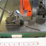
Aligning Using A Ground Cylinder
There are a couple of setup options for the measurement. A couple typical setups for setting square is illustrated to the left and right. Note that the indicator (in this case a DTI, though I could have used a dial indicator) is mounted in line with the base so that the adjustment knob on the base can be used to adjust the indicator’s reading.
You can use a setup with the ball end of the rod, as illustrated to the left, but it’s much less finicky to get an accurate zero if you use either an accurate round object (ball or cylinder) at the bottom, or a surface gage with a curved surface on the front. This larger curve makes it easier to dial in zero.
The process of dialling in zero is to slowly rotate the gage to find the high point against the known-square reference object. Then repeat the process on the blade. The excellent Youtube video below illustrates what you’re trying to do:

Indicator against blade
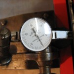
Dead-on 90°
To the right is the setup against the blade. I should mention here that you want to make sure to count the number of revolutions your indicator makes before zeroing when you dialled it in and then to count the revolutions when you put it against the blade, otherwise you can be significantly out of alignment.
Also, be sure to rotate the blade and check the measurement at multiple points in case the blade is warped. In my case it was fine.
There’s another way to check squareness that might be easier for some, though it won’t be quite as accurate: If you have a small, light square you can clamp it to the blade face and indicate off the top edge of the square to determine squareness. That method is illustrated in the 4 images below. Note that, because of the uneven distribution of weight on the blade, you can expect this to be less accurate, but it should still be more than accurate enough for most.. If you’re interested in calculating the actual measured angle, it’s 90±atan(heightdifference/lengthofsquare). It’s plus if the far end of the square is higher than the end next to the blade. Otherwise, it’s minus. In my case it calculated out to 89.981°.
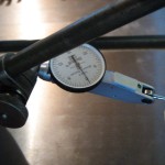
Indicating at tip
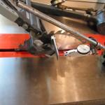
Square clamped to blade
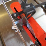
Another view

Indicating inside
Adjusting the blade stops will differ between different saws. Check your manual for instructions for your saw.
Checking the Blade’s 45° Stop
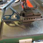
Combo square setting 45°
Next we check 45°. This one is essentially the same as 90°, though the initial setup can be a bit more difficult. You need an accurate 45° reference that maintains that 45° slope all the way to the bottom of the gage block – if, for example, you used a speed square where the tip didn’t come to a sharp point your measurement would be wrong.
Possibly the simplest option for this is to use a combination square, set up as shown to the left. Note that I’m using a known parallel surface (1-2-3 blocks) to raise the height of the surface gage so that the cylinder touches the angled portion of the square.
Now we just repeat the process as we did to set 90°, this time with the blade tilted to 45°.
Setting the Fence 90° to the Table
Again, this process is almost identical to setting the blade’s 90° stop. Just make sure to check both sides of the fence! If you note that they’re not parallel to each other remember to align the fence to 90° when moving it to the other side of the blade!
Aligning the Fence Parallel to the T-Slots
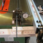
Aligning Fence to T-Slot
This process is very similar to aligning the blade to the T-slots. Set the gage up as before, bring the fence up so that the indicator is pre-loaded, and set it to zero. Move it down to the end of the fence and check runout.
As you did when setting the blade parallel to the T-slots you want to ensure that the runout opens up the width between the blade and fence towards the rear of the saw to guard against kickback. In my case I set the fence to have .003″ runout to the right at the rear of the fence. If I move the fence to the other side of the blade I’ll reset the runout (also compensating for the blade’s runout at the same time!)
Also, note the slip of wax paper under the surface gage. This helps it to slide on the table and prevents possible scratching.


