Assembling & Using a Homann Designs MP-03 CNC Pendant / MPG
Saturday, 23 April 2011
About a year ago I ordered a Homann Designs MP-03 Pendant kit to use with my NM-200. Before then I had used only a couple of other pendants and MPGs and decided on the MP-03 largely due to it’s expandability. Since them I’ve tried a few different units and I still am glad that I chose the MP-03. After getting the latest software (the original software had an issue that would make travel jerky) everything’s been smooth sailing. It’s been so good, in fact, that the touchscreen monitor I had originally intended to install to give me access to the mill controls from in front I haven’t even bothered with. I couldn’t live without the MP-03 now (well, I could, but I wouldn’t be using the machine very much).
I posted a writeup on assembling & installing the MP-03 shortly after purchase over at cnczone, but since things have been disappearing from over there I thought I’d re-post it here.
The Build
It took about 3 hours total for assembly. And that was with me being sick as a dog at the time. Realistically if I were well it would have taken maybe an hour and a half. If you’re a newbie to electronics projects this is a good place to start. You’ll want to have a decent soldering iron, some good solder (not the acid flux-cored stuff used for plumbing – you’ll probably be best with some rosin flux-cored solder), and a few hand tools like a screwdriver and some side cutters. You will also need to supply the wire for connecting the components in the case. 22-24 gauge will do nicely. The important thing with all of this is to take your time and it should be fairly straight-forward.
So before we delve into the build, what are the functions available for this pendant? Peter Homann covered this in this zone thread, which is actually where I first heard of it and became interested. You’d be well advised to check it out. I’ll highlight that besides the usual functions it has the ability to use custom functions.
So, on with it. Looking around online I found there really isn’t much on the actual build & install. There’s this page which isn’t complete yet, and a few posts here and there. If I could say there’s 1 problem with this kit it would be that it could be confusing to someone without electronics experience trying to assemble it. It’s supplied with a wiring diagram & some pics of the case and the parts mounted in it, but really that’s not where most would have a problem. It’s with the wiring. I could see someone who could finish this in a few hours spending days messing with it because of not being familiar with electronics. So hopefully this post will help any of those who may be around…
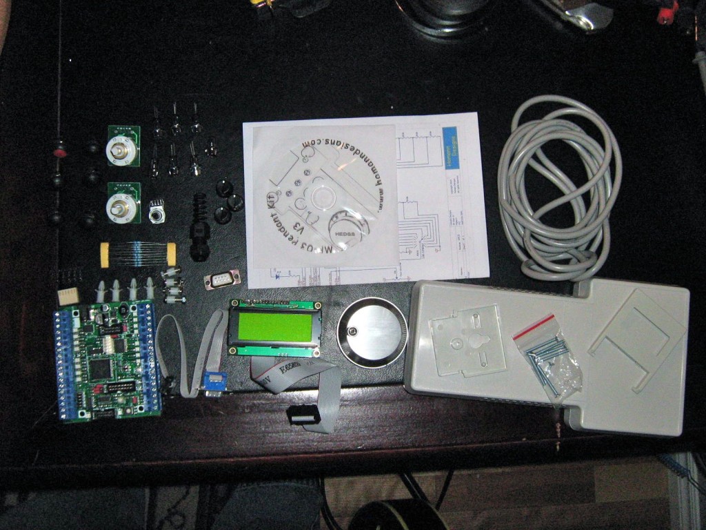
The first thing, if you’re like me, you’ll do when you get the kit is open it up and look at the goodies for a while. And here’s what you’ll see:
Now, if you wanted to get the kit routed you could have that done at purchase time for an extra $8. But I didn’t bother with that. Also note that you don’t necessarily need to order the LCD although I would DEFINITELY suggest buying this as it makes things much simpler and gives you the axis locations right there in your hand. You also could have ordered the optional “latching” E-stop switch, which you would then hard-wire as outlined in the Mach documentation to cut power to the axes & spindle. I had no need for the switch since I’ll be standing next to the hard-wired one on the mill. Without purchasing the latching E-Stop you still get a momentary software E-stop, which is going to be the red one in the picture.
So if you didn’t get the case routed that’s the first thing to do. Peter supplies some g-code files for the cutting, one for the latching E-stop and one for the momentary e-stop (don’t use the wrong one!). If you want to use his code you’ll need an 1/8″ endmill. He also provides a DXF if you want to generate your own. I just used his g-code. But note if you use the DXF that I found an error in the location of one or two of the holes. So if you use them check the drawings for alignment.
Assuming, though, that you just use his g-code you’ll want to start the mill at the right location. That’s illustrated in the image to the right. As you can see you’re going to want to start at the bottom-right corner as seen when looking at the front of the pendant. Note that it’s centered over the corner of the edge where the heights drop off for the recessed section. I zero’d the Z to the height at the recess first. The Kurt works fine for holding it as long as you’re confident in how much you should tighten it down. It’s actually sitting on the vise ways.
A couple of things to note regarding the actual cutting: I think, judging from some comments I’ve read by Peter elsewhere, that the g-code was generated to be milled on a Taig or Sherline. At any rate, the feed rates are VERY conservative, to the point I was afraid the plastic would start melting rather than cut.. I overrode it to 200% and it was better, though it probably could have been higher, so if you have the speed available you may want to manually edit the g-code to set appropriate speeds. The spindle speed was fairly low too, so that also affects things. If I were to redo it I’d probably look up the plastic type & the suggested feedrates. It’s also a very conservative DOC, doing most holes in 4 passes IIRC, including the final cleanup pass. Which was fine by me as I didn’t want it slipping out of the vise but if held tightly it could easily be cut in a single pass with a cleanup afterwards.
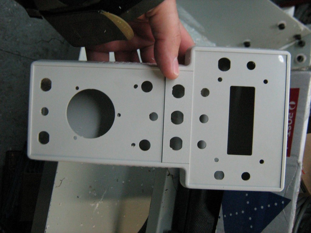
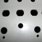
As for the second note, take a look at the part fresh off the mill first:
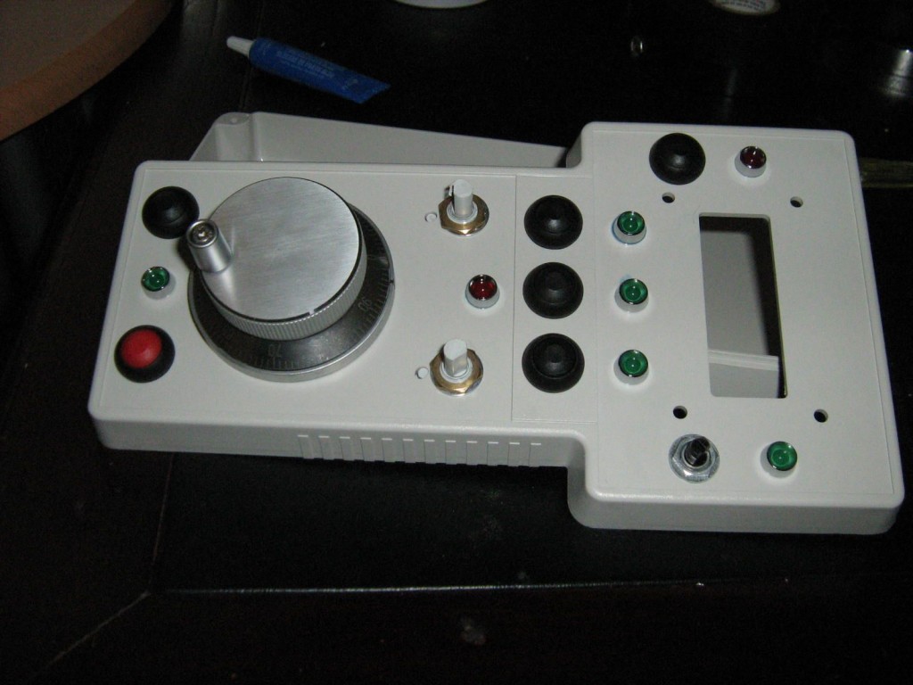
Notice the 2 small holes below 2 “medium” sized holes, just above the cutout for the rotary encoder. Look oblong? That’s because they are, but I have no idea why. I’m guessing because of the switches normally being installed slanted (see below). The code starts with a hole drilling, then moves at full depth on an angle for a short distance, probably about 1/8″. The finish location is the actual correct hole location. It’s for a locating pin for the 12 position switches. At any rate, if you want you can edit the G-code to remove this, though it doesn’t really cause much problem as it is covered.
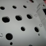
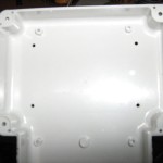
Now we need to do some modification to the inside of the top of the case (the part you machined). As just mentioned, if you installed the 12 position switches as-is they would be tilted because of 2 extrusions of the plastic. You can see what I mean in the Before pic to the left. If you were to install the switches they would sit on the round extrusions shown in the bottom of the picture. That’s no good. So to solve the problem cut them off flush, as shown in the picture on the right.
Next we modify the bottom of the case. You have the option with this kit to locate the ModIO board in the case or at the mill. I figured, as most seem to, that it’s easiest/best to locate it in the case & bring power up to it. If that’s what you’re doing you first need to locate, mark (sharpie works good) & drill 4 holes for the board (see the mounting orientation pictures later in this thread to get an idea of how to line the board up).
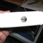
Before doing that, though, you need to remove 2 more extrusions. I didn’t realize this at first. I had intended to mount the board spaced off the back of the case with the little plastic mounting clips (similar to what comes with a motherboard) that came with the board. However there isn’t enough room to allow the case to close. So first remove these (pictured to the left), then mark & drill the case.
With that completed, drill the bottom of the case to accept the cable and anti-stress connection.
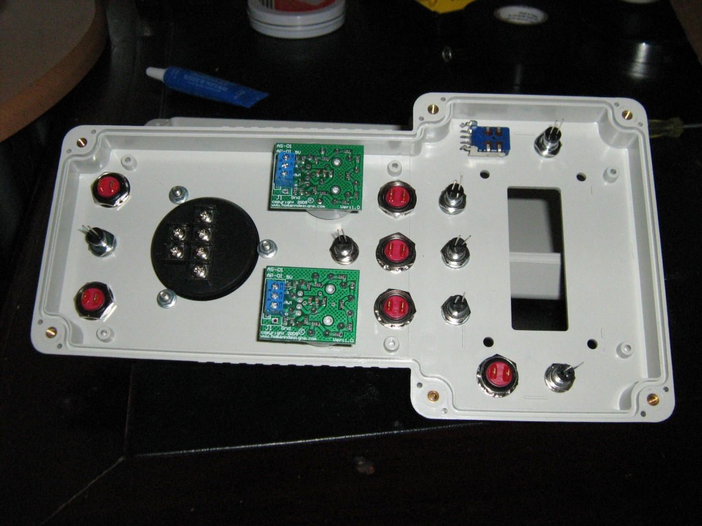
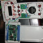
Next we can populate the top with the hardware. You only need to be aware of the location of the red pushbutton switch, and the red vs. green LEDs. I kept the anodes & cathodes of the LEDs oriented the same way for simplicity’s sake. Here are some pictures with the hardware installed:
Next we need to cut one lead of the resistors down and solder them on to the cut-down leads of the cathodes. If you don’t have much experience soldering here are a few tips:
- Use a real soldering iron. Soldering guns, while they will work, are clumsy and can wreak havoc with some components.
- Use an appropriately sized tip. If you use a tip that’s much too small or much too large you’ll be frustrated. Large tips have the obvious issue of getting in the way, but small tips have the more subtle problem of not producing enough heat to quickly melt the solder. This can lead to poor joints, frustration, and contrary to what we might expect, heat damage to components because of the extended exposure times.
- Keep the tip clean. A dirty tip, or one that’s covered in old solder, won’t work well.
- Tin the leads before trying to solder them together so you don’t need 6 hands to make the joint.
- Proper electronics flux can help the solder flow, but always clean up any excess. And never, never, never, use plumbing acid solder!
- If you have control over your iron’s heat settings make sure to use sufficient heat. Excess heat will shorten the life of tips but insufficient heat will drive you crazy trying to get the solder to flow. Start high and dial down to a comfortable level until you get used to the settings of your iron.
One thing of import to note that I would change if I built another unit: Instead of soldering the resistors so they rise vertically bend the resistor leads and the diode leads so they are leaving horizontally! I had originally thought that I would have more room in the case than I actually ended up with.
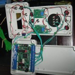
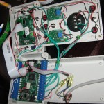
As I mentioned before you have to supply your own wiring. For simplicity’s sake I wanted to keep the wiring somewhat colour-coded. So I used red=+ve voltage, black=gnd, white=LED “signal” side, green = switch/pot signal. Below are some thumbnails of the wiring in progress. Click to enlarge.
In the 2nd photo from the left (red wires added) note that I pulled the +5V for these connections from pin 1 of J1 on the ModIO board. The +5V connection for the rotary encoder is not shown as I chose to pull that from +5V pin on J10. This isn’t strictly necessary.
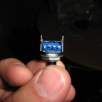
In the right-most picture you see the supplied potentiometer. This is a bit of an oddity. Typically you’d only see 3 pins. What’s with the 4 pins??? One is a dummy pin. I believe it’s the leftmost pin, but ohm it out to see for sure. If you’re not familiar with potentiometers, between the center pin (signal) and the other 2 “outer” pins you should get a rising resistance on one pair while you get a corresponding falling resistance on the other. The center pin goes to pin 5 of the ModIO. One of the other 2 gets +5V, the other ground. Which gets which? It depends on the logic, if it’s going high (+5v) or low (gnd). If you wire it wrong the pot will work backwards. I actually had this problem. Just switch the wires around.
Notice in the 3rd photo from the left that the ModIO card is now mounted. I’d suggest for when you’re doing this that you remove the screw terminals from the board (the blue strips on top & bottom). They pull up as a long strip – work it a little at a time from either end. Then when you get it wired you can plug it back in.
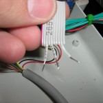
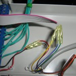
Once you get all that done you can install the serial cable into the bottom hole you drilled for it (through it’s holder/tail, obviously). Now we get to wiring the signal lines for the rs-232 & the power lines. Again I chose red & black for power, and arbitrarily chose blue, yellow, green for signal. For simplicity’s sake (and because I didn’t have a second one available to use for connecting to the PC) I chose to cut off the 9 pin serial connector and wire it directly to the cable. Hence at the right you see the equivalent of pins 2, 3& 5 (from L-R) exposed on the 10 pin wire from the header on the ModIO board. Also, in case you’re not aware, the pins in the cable bounce back & forth from the top row to the bottom, so 1, 6, 2, 7, 3, etc.
To the right is the communcation & the power supply wired. I used some more single-strand wire to go from the serial cable to the screw terminals because I was concerned the wire from the serial cable wouldn’t hold in the screw terminal. Note that if you end up using crimp connectors you’ll need to supply them!
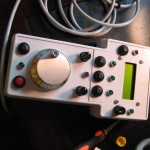
Finally we have the LCD installed and everything closed up. A couple of brief notes are in order: First, when you’re closing everything up you may get frustrated with the massive amount of wiring inside. Hopefully you’ve been careful in routing the wires together, but in addition if you have some electrical tape or, even better, Kapton tape you can use that to hold the wiring in position while everything’s being closed. Then, as the lid is closing, use a small item like a dental pick or a small screwdriver to realign anything that starts to move on you. Secondly, the 2 knobs on the multi-position switches don’t quite fit all the way down. Because they’re slightly offset (due to the set screw that holds them in place) they will hit the nut. The simple solution is to mount them carefully on the mill or lathe and enlarge the hole in the bottom. Be careful with whatever workholding system you use, though, as they are quite fragile.
Now we get to the NM-200. I drilled a hole in the bottom of the electronics cabinet, installed a grommet, and
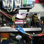
ran the wiring in. As I have a different coolant system with an external reservoir (read: garbage bucket – works great!) I ran the wiring through the hole in the stand that was made for the table drain outlet (it now drains directly into the garbage bucket), through the stand and out through a hole in the rear. The wire then went straight up through the grommet into the cabinet. On both sides (inside & outside) of the grommet I installed a couple of small zip-ties to keep the cable from being pulled in to or out of the cabinet. I ran the wiring up to around the area of the serial port & connected the wiring via crimp connectors to match the signal lines in the pendant. But what about power? The manual specs 8-24V DC or 6-12V AC supply, with higher voltages risking higher heat produced in the case. The easiest source for this is the computer’s power supply. Cut a yellow & black line (one at the end of a run so it doesn’t have 2 wires going in to it – otherwise everything past that connector will be dead), attach a couple of connectors, and you’ve got power. Alternatively, and even better, would be to use one of those molex power adapters typically seen on auxillary case fans, which usually run at 12V, such as seen on this fan from Newegg. I literally used to have hundreds of them when I was doing some different work. Unfortunately I don’t have any lying around anymore, and there’s no local source. So the plugs it is!
From there it’s just configuring the software. The “driver” is on the included CD. That said, I couldn’t get into the configuration manual without first running through the Getting Started section of the ModIO manual (up to the point of hooking up some LEDs, and note that I didn’t bother making a copy of the configuration). Then you can go into the plugin configuration, click help, and it walks you through all the rest of the steps. Sweet!
Configuration and Modification
You should now have the pendant controlling the mill. You can do a lot with it as-is, but the real power of this system is that you can customize everything to your heart’s content. This post isn’t really for the purpose of delving into everything that you can do. For that you’ll want to read some documentation on Mach3 and ModBus. But I’ll mention a few basic things I did.
First of all, in order to get the multiposition switches to work right I had to modify the resistance values in the pendant’s software screen as there was some overlap (basically the SW is looking for a resistance in a range, say 200-1200 ohms, for position 1, and the switch’s PCB simply adds resistors as you turn the knob. So if position 1 is 1150 ohms actually read in the pendant’s screen set it’ll be so close to the next switch that it can cause the software to think you’re on position 1 instead of 2). This was a very simple thing to do, but I was getting Y and Z randomly swapping back and forth when I first was trying to jog the axes.
Next, the pendant’s LCD screen only changes the function display when the left switch moves. To display the right-switch position options you can modify the screen set to output a display somewhere on the screen. Just open up your desired Mach screen editor (such as MachScreen), insert a label (In MachScreen select Label as the Control type in the drop-down menu in the MachScreen properties window, select Add, and click where you want to put it. If you need to move it hold shift while selecting it). Make the label large enough and adjust colours as necessary. With the label still selected double-click the Label field in the Label box and type UserLabel220. UserLabel220 is set to display the right-switch position info.
Probably the biggest thing you’ll be wanting to do is to create custom functions to run from your pendant. For example, the 2 most used on mine are Goto Zero and Auto Toolsetting. In essence any command that you can set up to run by a button on the Mach3 window can be ran from the pendant. I won’t go into detail on how to set custom commands up – looking up auto Z toolsetter for Mach3 will give you lots of posts about that elsewhere – but I will give you a brief idea of the extra steps to get this to work with the MP-03. First, in the MP-03 plugin config window go to Left Switch and put an appropriate user message in one of the locations. For example, I have 9th Pos. Button A set to “GoZero”. Note that 6 characters is the max. Also note the ULED for control – in this case 2001. Next, go to Operator, Brain Editor. We’re going to set up a simple brain, which is basically a ladder logic program if you’re familiar with that. Name it something appropriate. Next click +, choose to add an LED, check the box next to Use LED number and type in 2001. Click OK. A box entitle OEMLED2001 will appear on the leftmost side of the window. Select the box until it turns green to highlight that lobe and press + . This brings up the lobe logic box. Since we just want input from the button (OEMLED2001) to zero the axes we don’t need any logic, so select “No Operation” to pass through the command uninterpreted. You’ll see a second box connected to the first with “No Operation/Pass signal” written inside. Highlight that box as you did the first (it, too, will be green) and click on the green inverted T to terminate the lobe. This is where you tell it to do whatever command you wish to run. You don’t need a button on the screen for this to work, but in this case we have one so go to ButtonPress and select 1017-GotoZero’s. Your previously selected box is now connected to a red box all the way on the right side. Save the file. Back in Mach3 go to Operator, Brain Control, select the brain (click reload all brains if necessary) and check enabled. Rotating your left switch to the proper position and pressing the appropriate button under the LCD should now perform a GoTo Zero command!
As well, you may want to put an overlay on the pendant to let you know what everything’s for. While waiting for an opportunity to get some proper overlays printed up I decided to print out a sample on a transparent label. It’s still holding up so I still haven’t printed a proper one! So if you want a cheap overlay you can use/modify my dxf, below, and print it on a transparent label, cut it out, et voila!
